Artillery
rocket system mounted on a tracked vehicle.
Features: The Multiple Launch Rocket
System (MLRS) is a free-flight artillery rocket system that delivers
large volumes of firepower in a short time. The system is used to
attack enemy artillery, materiel and personnel targets and suppress
enemy air defenses. It consists of a launcher, two disposable pods,
each containing six rockets or one missile, a fire control system, and
an aiming device. The carrier is a derivative of the Bradley Fighting
Vehicle.
Background: The Army received the MLRS
in 1983. There are currently 528 launchers and 373,668 rockets in the
Army inventory. At the completion of the planned buy, the Army will
have 1,623 launchers and 481,110 rockets. The basic warhead carries
dual-purpose improved conventional submunitions (bomblets).

Launcher
and Subsystems:
M270 Launcher: The M270 launcher is a
highly mobile, lightly armored, tracked carrier vehicle with a
launcher-loader module (LLM) mounted on the vehicle bed (see Figure
1-1). The launcher consists of a three-man crew (section chief, gunner,
and driver). Personal equipment is stored in the crew's equipment
storage containers located in the carrier under the LLM cage.
The M270 launcher has two major configurations. The US has a system
that can fire rockets and missiles; the memorandum of understanding
(MOU) nations have M270 launchers which can only fire rockets. The
difference between them is the payload interface module (PIM), a new
stabilization reference package/position determining system (SRP/PDS)
and software special applications packages (SPAPS).
M993 Carrier Vehicle: The carrier
vehicle is a longer version of the Bradley fighting vehicle with nearly
80 percent common components. It is 6.3 meters (m) (22 feet [ft] 11
inches [in]) long, 2.6 m (8 ft 6 in) high, and 2.97 m (6 ft 9 in) wide.
When heaviest (loaded with M26 rocket LPCs), the launcher weighs
approximately 24,036 kilograms (kg) (52,990 pounds). It can climb 60
percent slopes, traverse a 40 percent side slope, ford 1.1 m (40 in) of
water, and climb 1 m vertical walls. The launcher has a cruising range
of 483 km (300 miles) and can be transported by C-14lB and larger cargo
aircraft.
The vehicle cab is constructed of aluminum armor plate, providing
ballistic protection to the crew. It is fitted with an M13A1 gas
particulate filter unit that protects the crew from chemical and
biological agents and radioactive particles. It also has a vehicle cab
overpressure system to protect the crew from toxic rocket and missile
exhaust.
M269 Launcher-Loader Module: The LLM
consists of two sections--a mechanical section and an electrical
section. These sections work together in order to perform all firing
and non-firing functions.
LLM
Mechanical Section: The mechanical section consists of base,
turret, and cage assemblies. The base assembly provides for the
physical mounting of the LLM to the carrier. Both the turret and base
assemblies house the electronics and hydraulics of the launcher drive
system (LDS) that actually perform the rotation and elevation functions
the LLM. The cage assembly performs two important functions. First, the
structure of the cage assembly aligns, holds, and protects the launch
pods. Second, two boom and hoist assemblies mounted in the cage
assembly give the launcher crew a built-in ammunition loading and
unloading capability.
LLM
Electrical Section: The electrical section consists of three
subsystems: the primary power supply, the communications system, and
the FCS.
Primary
Power Supply: The primary power supply is the source of power for all
launcher equipment. It uses standard military lead acid batteries to
provide 24 volts of power to the launcher components. It also controls
the distribution of power through the use of switching relays.
Communications
System: The launcher communications system includes a secure -12 series
frequency modulated (FM) radio and one communications mode selector
control (CMSC) device or the newer singlechannel ground and airborne
radio system (SINCGARS) AN/VRC-92A radio system with embedded
communications security (COMSEC) capability. The CMSC detects an
incoming signal, determines whether it is digital or voice traffic, and
automatically routes it to the secure FM radio in the proper mode for
decryption. The CMSC is not required if using SINCGARS with embedded
COMSEC. Each crew member has a combat vehicle crewman (CVC) helmet that
is connected to an AN/VIC-1 intercom system.
Fire
Control System: The FCS functions with the other launcher components to
provide overall control of the LLM. It monitors, coordinates, and
controls all electronic devices used during a launch cycle. The FCS
consists of the fire control panel (FCP), electronics unit (EU), fire
control unit (FCU), boom controller (BC), short/no-voltage tester
(SNVT), SRP/PDS, PIM, program load unit (PLU), and communications
processor (CMP).
Associated
Equipment
Ammunition
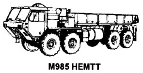
Resupply Vehicle and Trailer (HEMTT/HEMAT): The M985 HEMTT is
a 10-ton, 8-wheel or 8-wheel-drive truck with a 5,400-pound lift
capacity materiel-handling crane. A secure FM radio provides voice
command and control capability. The rearmounted crane can traverse
360° to the left or right. Both the HEMTT and the HEMAT can be
loaded and unloaded with the crane. The HEMAT does not have to be
unhooked from the HEMTT. The truck carries four launch pods with a
gross vehicle weight of 59,000 pounds.
Its
operating range is 300 miles, and it can climb a 30 percent slope. The
HEMTT has a 445-horsepower diesel engine with an automatic
transmission. It can be transported by C-130 and C-141B aircraft in an
unloaded configuration and by C-5A/C-5B aircraft in a loaded tactical
configuration.
The M989A1
HEMAT can carry four launch pods and has a fully loaded gross weight of
31,000 pounds (see Figure 1-10). The trailer can be towed by a launcher
in an emergency.

Command,
Control and Communications System: Tactical command and
control and technical fire direction of MLRS units is provided through
a C3 system. The C3 system includes the radio system, FED, FCS, FDS,
and in some units, the FDDM. This system is designed to be integrated
with several Army and Air Force command, control, communications, and
intelligence (C3I) systems to optimize fire support system employment
and effectiveness. The MLRS C3 system also can be used to conduct and
execute command and control without external C3 input during
independent operations. This independent C3 capability exists at
battalion, battery, and platoon levels. The hub of the MLRS C3 system
is the MLRS FDS and FDDM. The FDS/FDDM can communicate digitally with
the following systems:
M270
FCS - The
Tactical Fire Direction System (TACFIRE, LTACFIRE, and MCFSS)
- The
Advanced Field Artillery Tactical Data System (AFATDS)/li>
- Firefinder
Radar (AN/TPQ-36 and AN/TPQ-37)
- Meteorological
Data System (MDS)
- Meteorological
Measuring Set (MMS)
- Initial
Fire Support Automated System (IFSAS)
- The
Forward Entry Device (FED)
Fire
Direction System The MLRS Fire Direction FDS provides tactical fire
direction and data communications for command and control at the MLRS
platoon, battery, and battalion. Initialization procedures define the
FDS capabilities for the specific echelon. The FDS (AN/GYK-37) consists
of the lightweight computer unit (LCU), tactical communications
interface module (TCIM), the AC/DC converter/charger, the TCIM wireline
adapter, and the printer (see Figure 1-11).
System
Components:
M270
Launcher: Each launcher has the onboard capability to receive
a fire mission, determine its location, compute firing data, orient on
the target, and fire. Each bay of the launcher must be loaded with the
same type munition. Once laid and armed, the launcher can fire:
- Twelve
rockets in less than 60 seconds at up to six aimpoints.
- Two
missiles in less than 20 seconds at one or two aimpoints.
Launch
Pod/Containers and Guided Missile Launch Assemblies: Each
launch pod container (LPC) holds six rockets, and each guided/missile
launch assembly (GMLA) holds one missile. The pods are stenciled with
the DOD identification code (DODIC). This is the same code that is
displayed on the fire control panel (FCP) when ammunition status is
displayed to the M270 crew members.
Ammunition
Resupply Vehicles and Trailers: The ammunition resupply
capability for MLRS is provided by the heavy expanded mobility tactical
truck (HEMTT) M985 and the heavy expanded mobility ammunition trailer
(HEMAT) M989/M989Al. Each one can carry four rocket/missile pods for a
total of 48 rockets or eight missiles in a HEMTT and HEMAT load (the
HEMAT M989 is limited to two launch pods during peacetime operations,
but the HEMAT M989A1 does not have this limitation).
Command,
Control, and Communications System: The MLRS has an automated
command, control, and communications (C3) system to provide command and
control of subordinate launchers and to facilitate communication on the
battlefield. Major components of the C3 system are the fire control
system (FCS), located in the launcher, and the fire direction system
(FDS), located at the platoon. Only selected batteries and battalions
have the fire direction data manager (FDDM).
MLRS
Family of Munitions
Launch Pod: Each M270 holds either two
LPCs or two GMLAs (not a mix of the two) in the LLM (see Figure 1-3).
Each launch pod contains either six rocket tubes or one missile housing
in a containerized shipping, storage, and launch frame. Rockets and
missiles are factory assembled and tested. Rockets are stored in
fiberglass containers; missiles are stored in an aluminum enclosure
with fiberglass camouflage panels on the exterior. Both rockets and
missiles are then mounted on the frame. Both the rocket tubes and the
missile housing are connected by cable to common electrical connectors.
Not only are handling, transport, and loading fixtures similar, the LPC
and GMLA are also visually similar.
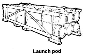
The launch
pod is 4.04m (13 ft 2 in) long (without skids) and 1.05 m (3 ft 5 in)
wide. The height of the pod is 0.84 m (2 ft 9 in) with skids and 0.72 m
(2 ft 4 in) without skids. When loaded with rockets (tactical or
practice), each LPC weighs 2,270 kg (5,005 pounds). A loaded GMLA
weighs 2,095 kg (4,609 pounds), and an inert training GMLA weighs 1,360
kg (2,998 pounds).
Four
aluminum bulkheads provide rigidity to the frame and support for the
rocket tube or missile housing. Tiedown and lifting D-rings are located
on the top of the frame at the four corners. A lifting rod is installed
for lifting the container by the launcher boom and hoist assemblies.
Stacking
pins at the top four corners of the frame permit stacking of the launch
pods. They can be stacked two high during transport and four high
during storage. They can be handled by forklift, since they have two
inner bulkheads that serve as support members. Each launch pod is
marked for the center of gravity and proper lift areas.
The
detachable skids mounted to the bottom four corners of the frame must
be removed from the pod before it is loaded into the LLM. A
quick-release pull pin allows easy removal of the skids. The GMLA also
has a lifting rod cover which must be removed before being loaded into
the LLM.
The
changing of rocket and missile pods requires a repositioning of the
loading hoist assembly system.
Rockets:
The MLRS rockets are tube-launched, spin-stabilized, free-flight
projectiles. The rockets are assembled, checked, and packaged in a
dual-purpose launch-storage tube at the factory. This design provides
for tactical loading and firing of the rocket without troop assembly or
detailed inspection. Major components of the rocket assembly include
four stabilizer fins, a propulsion section, and a warhead section.
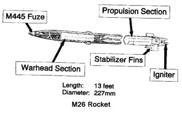
Propulsion
for the rocket is provided by a solid propellant rocket motor. An
umbilical cable, passing through the aft end of the launch tube, links
the FCS to an igniter in the rocket nozzle. The motor is ignited by an
electrical command from the FCS.
Each
rocket is packaged with the four fins folded and secured by wire rope
retaining straps. As the rocket moves forward upon firing, lanyard
devices trigger a delayed strap-cutting charge. After the rocket leaves
the launch tube, the charge cuts the straps. This allows the fins to
unfold and lock. The M28 and M28A1 rockets' LPCs have an additional fin
release device to ensure deployment.
The
MLRS rocket follows a ballistic, free-flight (unguided) trajectory to
the target. The propulsion provided by the solid propellant rocket
motor is the same for each rocket, so rocket range is a function of LLM
elevation. The four stabilizer fins at the aft end of the rocket
provide in-flight stability by maintaining a constant counterclockwise
spin. The initial spin is imparted to the rocket through spin rails
mounted on the inner wall of the launch tube.
M26
Rocket: This is the basic rocket for MLRS. It is used against
personnel, soft and lightly armored targets normally with a target
location error (TLE) of 150 m or less. Larger TLEs may reduce
effectiveness. Each rocket dispenses 644 M77 dual-purpose improved
conventional munitions (DPICM) submunitions over the target area.
Warhead
event is initiated by an electronic time fuze (M445) that is set
remotely by the FCS immediately before ignition of the rocket motor.
The fuze triggers a center burster charge. This causes the warhead to
rupture, the polyurethane filler to shatter, and the submunitions to be
spread over the target area.
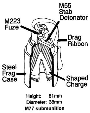
M77
Submunition Description: The armed M77 submunitions detonate
on impact. The antimateriel capability is provided through a shaped
charge with a built-in standoff. The M77 can penetrate up to four
inches of armor. Its steel case fragments and produces antipersonnel
effects with a radius of 4m.
Extended
Range Rocket: The extended range (ER) rocket is an evolution
of the basic M26 rocket that extends the range to 45-plus km. This
greater range capability is achieved through a 20 percent reduction in
the number of submunitions and a modified rocket motor. It has at least
the same accuracy as the basic M26 rocket. ER-rocket accuracy is
enhanced by an improved rocket detent located in the launch tube.
Additionally, the wind measuring device (WMD), a component of the
future Improved FCS, updates the firing solution prior to launch at the
firing point with corrected low level wind readings. The effectiveness
of the M26 rocket is maintained in the ERrocket even though the
submunition payload has been decreased. This is due to the improved
center core burster and a reduction in the dud rate, made possible by
an improved drag ribbon design and the incorporation of a self-destruct
fuze.
Missiles:
The Army TACMS missiles are ballistically launched, inertially guided
missiles. They are designed to carry a variety of submunitions, to
include "smart" munitions and lethal mechanisms to provide a wide range
of future capabilities. Currently, the Army has only the M39 missile.
Missile
Assembly: The missile has four sections: the guidance and control
section, propulsion section, control section, and the warhead assembly.
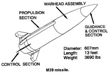
Guidance
and Control Section (GCS): The GCS provides all navigation, guidance,
autopilot, and internal communications functions for the Army TACMS
missile while in flight and for all ground operations. Continuous
determination of position, attitude, and motion are provided by the
inertial sensors, associated electronics, and software processing.
Guidance and autopilot functions are provided by software processing
within the GCS computer. All communications, both internal and external
to the missile (missile to launcher and/or ground support equipment),
are provided by the GCS electronics and software. This includes
communications with the M270 FCS electronics for launch control, the
ground support equipment for maintenance, and the control system
electronics unit (CSEU) for missile fin actuator control.
Propulsion
Section: The solid rocket motor furnishes the energy necessary to
launch the missile and sustain missile flight for a sufficient time to
meet Army TACMS altitude and range requirements. The solid rocket motor
consists of a motor case, propellant, insulation/liner, nozzle, and
igniter arm/fire assembly.
Control
Section: The primary functions of the control section assembly are to
position the missile fins, provide the missile electrical power while
in flight, and support selected pyrotechnic functions.
Warhead
Assembly: The primary function of the warhead assembly is to carry,
protect, and dispense the missile payload. The warhead assembly
consists of a rolled aluminum shell with aluminum support structures
and front and rear bulkheads. A center tube connects the bulkheads and
provides a central wire route. In addition to the payload, the warhead
assembly contains a skin severance system which controls the release of
the payload at the required time.
Army
TACMS Block IA: The Block IA missile carries approximately
300 M74 bomblets. A GPS receiver will be integrated into the missile
which allows it to receive positioning data updates for increased
accuracy. The Block IA missile ranges targets from 100 to 300 km.
Army
TACMS Block II: Block II employs the brilliant antiarmor
technology submunition (BAT). The Block II missile ranges targets from
35 km to 140 km. The Block II payload consists of thirteen BAT
submunitions which are equipped with both acoustic and infrared sensors
that give each submunition the capability of acquiring and attacking
moving armor targets. After the dispense from the main warhead, each
BAT submunition autonomously seeks an individual target within a moving
armor column with its acoustic sensor. Once each submunition is close
enough to its selected target vehicle, the inbred seeker is activatated
and provides guidance during the terminal trajectory. The BAT
submunition has a tandem shaped charge warhead designed to defeat all
known reactive armor.
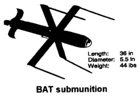
Army
TACMS Block IIA: Block IIA employs an improved BAT
submunition that is effective against both hard and soft, moving and
stationary targets. The Block IIA payload consists of six improved BAT
submunitions which are equipped with sensors that give each submunition
the capability of acquiring the target regardless of whether an inbred
signature exists. The improved BAT submunition has a multipurpose
design to kill both hard and soft targets at ranges that exceed the
Block II missile.
|

